Plans / DRAWINGS
Our town planners can assist with the Design & Construction Plans/Drawings for all types of projects (residential / retail / commercial / industrial). Types of drawings / plans include, but are not limited to, the following:
- Location Plan
- Site Plan
- Floor Plan
- Elevation Plan
- Section Plan
- Shadow Diagrams
- Stormwater Drainage Plan
- Erosion & Sediment Control Plan
- Survey Plan
- Landscape Plan
More details and example of the more common plans are available below. Contact TRANPLAN Consulting to discuss any Design & Construction Plans/Drawings requirements for your project.
Site Plan
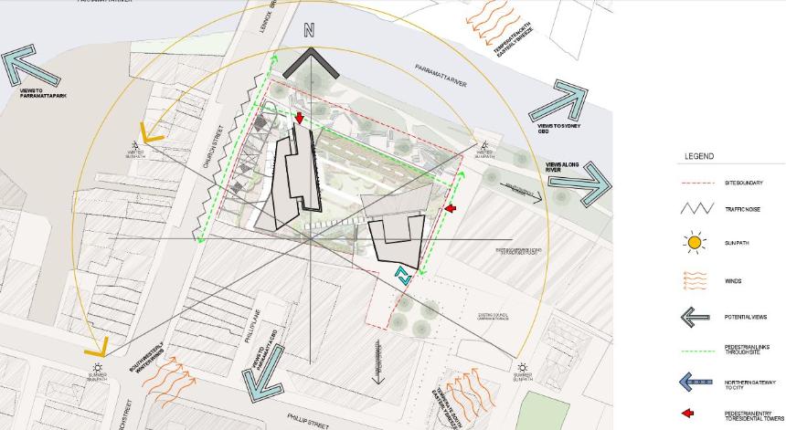
A site plan is a plan showing the whole context of a building or group of buildings. A site plan shows property boundaries and means of access to the site, and nearby structures if they are relevant to the design. For a development on an urban site, the site plan may need to show adjoining streets to demonstrate how the design fits into the local area. Within the site boundary, the site plan gives an overview of the entire scope of work. It shows the buildings (if any) already existing and those that are proposed, usually as a building footprint; roads, parking lots, footpaths, hard landscaping, trees and planting. For a construction project, the site plan also needs to show all the services connections: drainage and sewer lines, water supply, electrical and communications cables, exterior lighting etc.
Site plans are commonly used to represent a building proposal prior to detailed design; a tool for deciding both the site layout and the size and orientation of proposed new buildings. A site plan is used to verify that a proposal complies with local Council controls. In this context the site plan forms part of a legal agreement, and there may be a requirement for it to be drawn up by a licensed professional: architect, engineer, landscape architect or land surveyor. An example of a site plan is below.
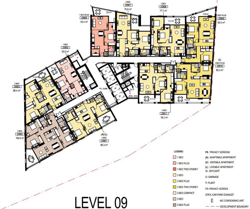
Floor Plan
A floor plan is the most fundamental architectural plan, a view from above showing the arrangement of spaces in building in the same way as a map, but showing the arrangement at a particular level of a building. Technically it is a horizontal section cut through a building (conventionally at four feet / one metre and twenty centimetres above floor level), showing walls, windows and door openings and other features at that level. The plan view includes anything that could be seen below that level: the floor, stairs (but only up to the plan level), fittings and sometimes furniture.
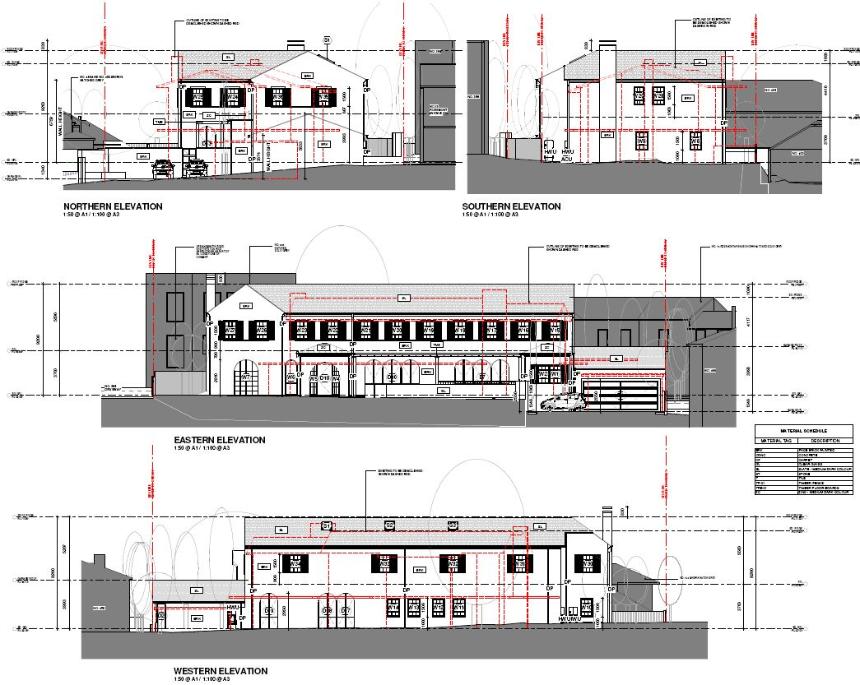
Elevation
An elevation is a view of a building seen from one side, a flat representation of one façade. This is the most common view used to describe the external appearance of a building. Each elevation is labelled in relation to the compass direction it faces, e.g. looking toward the south you would be seeing the northern elevation of the building i.e. the north elevation is literally the north-facing wall of the building.
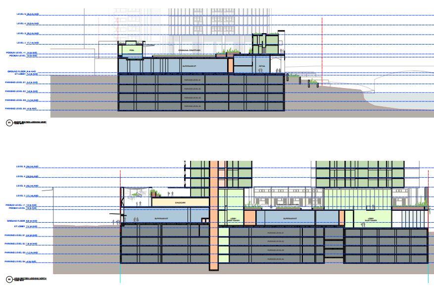
Cross section
A cross section, also simply called a section, represents a vertical plane cut through the object, in the same way as a floor plan is a horizontal section viewed from the top. In the section view, everything cut by the section plane is shown as a bold line, often with a solid fill to show objects that are cut through, and anything seen beyond generally shown in a thinner line. Sections are used to describe the relationship between different levels of a building.